
Background:
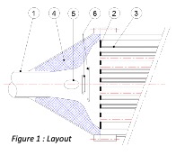
Transfer Line Exchangers (TLE’s) are applied widely in industry in the process of ethylene production. Its function is to rapidly quench the effluent gas from the radiant coils of ethylene cracking furnaces. The equipment, referring to Figure 1, are typically described by a high gas velocity inlet (1), a tube-sheet (2) and tube-coils (3) with cooling liquid on the shell side. The inlet must achieve the shortest possible residence time and rapid cooling by expanding the flow from the high velocity inlet to the larger diameter tube-sheet – the TLE inlet is typically fitted with a ‘bell-house’ shaped refractory (4) to minimize recirculation zones and attempt uniform flow distribution to the tubes. An Intrabody Flow distributor (IFD) consisting of a center body (5) and flow vanes (6) having unique size, location and angles to mitigate coking, erosion and flow distribution problems, are discussed below.
PROBLEM:
TLE’s often limit production and incur maintenance costs for its owners and operators by failures or unplanned shutdowns for required decoking and mechanical cleaning. Specifically, problems include (i) Coke build-up on the inlet cone refractory, on the peripheral tube-sheet face and in the tube inlets, and (ii) Erosion of the tubesheet by flow impingement on the central zone. These problems result in increasing pressure drops and a reduction in heat transfer – a classic ‘snowball’ cascading effect.
SOLUTION:
Knighthawk Engineering (KHE) has significant experience in developing a 3-step customized solution, specific to the TLE design and process conditions, drastically improving the performance and run times of TLE’s.
STEP 1:
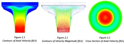
Step 1 is by CFD analysis – Figure 2, at left, shows typical contour and vector plots of the high velocity impingement on the central tubes, inadequate distribution to the peripheral tubes and the large recirculation zone in the flow expansion cone region. Excessive coke buildup in this recirculation zone, metal losses by flow impingement and erosion of the central tube sheet and poor flow distribution to the periheral tubes are evident.
Notably, in performing this type of analysis, it is important to accurately model the tube pressure drop over the system from measured data. Also, the flow composition with pressure-temperature dependent properties, turbulence model applied, mesh refinement, boundary layer and specifically the wall Y+ must be accurately applied to ensure quality of results by CFD analysis. 3D flow effects from upstream elbows and inlet conditions must often be taken into account where applicable.
STEP 2:
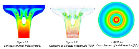
Step 2 is by designing a solution in an iterative and comparative development. Refractory shape, IFD centerbody and flow vane size, angles and locations must be optimized so as not to increase pressure drop yet minimize or eliminate the flow recirculation, mitigate center impingement and improve distribution to periheral tubes.
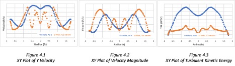
Figure 4 below shows XY plots, linearized over a tube-sheet cross section with the solution IFD case plotted in lighter (orange) dots. The Y velocity (Fig. 4.1) shows reduction in the central peaks, Fig. 4.2 shows the shift in velocity magnitude to peripheral zones and Fig. 4.3 plots the reduction in turbulent kinetic energy. This modification presents no additional pressure drop, decreased residence times in the inlet cone by magnitude 10% and decreased turbulent kinetic energy as a proxy of erosion intensity by a factor 2 over the tube sheet face. Also, the recirculation zone on the refractory cone was drastically reduced.
STEP 3:
KHE manufactured and delivered the IFD complete with its rods and fitting for attachment to refractory cast.
IN SUMMARY:
- Defining the problem and developing a high-fidelity CFD model including calibration to operating data and specific to the geometry and process conditions.
- Developing a solution by closely collaborating with the client engineering, maintenance and production personnel.
- Manufacturing and delivering an IFD unit from high temperature and erosion resistant materials, with a proven track record in industry.