
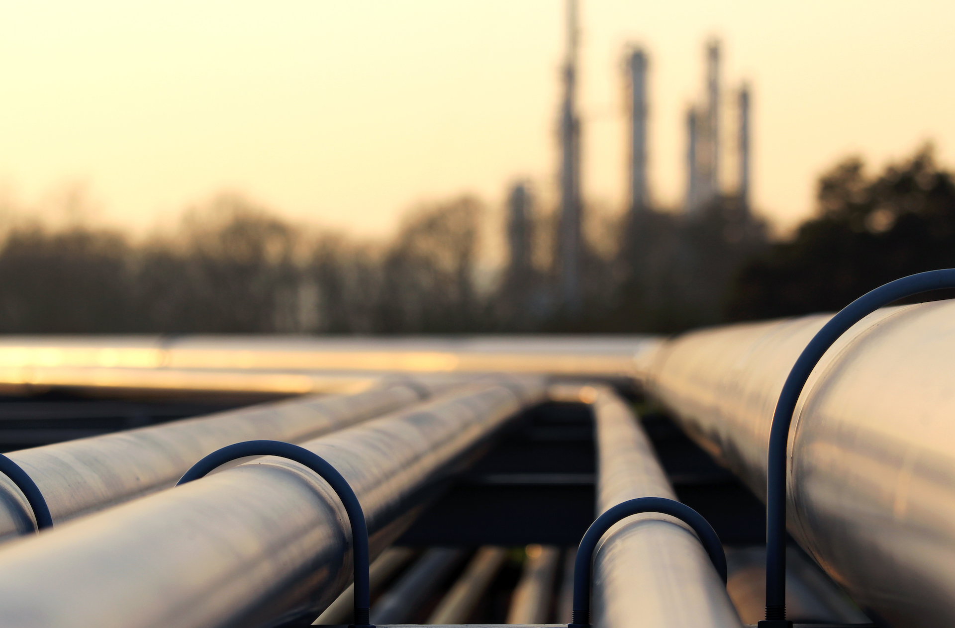
Your Situation: Possible Pipe Damage
Once again, the operators at your production facility have approached you about a 1,600-degree Fahrenheit line where the pipe shoe has detached from the structural steel and jammed against a beam, causing a failure of the structural steel. While working in operations, you have heard from the “old timers” that this happens every two or three years. As the production engineer in charge of the area, your main concern is the failure of the pipe or breach of process containment, as the loss of hydrocarbons would be of great concern. When one of the operators is on a coffee break, you ask him to determine — to his best recollection — when this last happened. After that, you look at historical-run data and determine this has occurred most often when there were more frequent shutdowns. The next step is to talk to the plant engineering folks about the design. They say a pipe-stress analysis has been run by the engineering contractor — it was examined and audited — and no pipe-stress problems were found.

Thermal Walking – Permanent Deformation
This event is common in plant operations where piping experiences remarkable thermal growth and the piping system is analyzed by an elastic approach. The piping undergoes what is called “thermal walking.” When the plant shuts down, the pipe does not return to its original position. When a subsequent thermal cycle occurs, the pipe would simply displace further. An elastic pipe-stress analysis cannot determine a condition of thermal walking because “elastic” means it will return to its original position. Thermal walking in piping systems has led to failure of piping systems and caused remarkable events at production facilities. The piping in question was operating in the elastic-plastic region. This means the pipe was operating within the stress-rupture curves, and with each thermal cycle, it experienced permanent deformation. Such a system is deemed “critical pipe stress” because of the operating pressures and temperatures.
Our solution: Finite Element Method
Such a problem is best analyzed using the finite element method (FEM), which considers the plastic deformation of the pipe. In years past, this was unthinkable and considered too costly, but that is no longer the case with the advanced software and computing horsepower available today. Now pipe-stress models can be created using FEM, and accurate responses can be developed for critical pipe-stress situations in a relatively short period of time. The other significant advantage is that the FEM captures localized secondary stress in piping components, which typical elastic-based software does not. In the FEM, both a heat-transfer and structural stress analysis are performed to obtain accurate results.
The following steps are a methodology for tackling critical pipe stress:
- Develop a process specification on what the operation and design conditions will be. This includes startup and shutdown operations.
- Consult with a materials engineer to determine the best material for the application, considering both reliability and economics.
- Develop an elastic pipe-stress model to determine the required overall layout.
- Execute an elastic-plastic model to consider the plasticity effects in the system.
- Install supports and limit stops to control any anticipated thermal walking. This might involve putting in an entire floating system.
- Refine the model to look at secondary stress points such as piping hardware attachments. You should also consider welded joints where there is a change in the material composition. These can be considered in the FEM as well.
- Perform a detailed check and inspect the line after startup to ensure it is behaving as anticipated.
As with any critical application, make sure the design is supervised and approved by a professional engineer who is competent in this area of expertise.